Select the perfect flow meter for your application
This flow meter selection guide helps you understand how to choose a flow meter and how to select a flow meter for gas or liquid applications.
Choosing the right flow meter depends on more than just the required flow rate.
The measured medium, flow range, accuracy, pressure, temperature, material compatibility, and required output all play an important role.
At Mass Flow Online, we offer flow meters for both gases and liquids, using different measurement technologies to match a wide range of industrial, laboratory, and process applications.
Our portfolio includes thermal mass flow meters, magnetic flow meters, and variable area flow meters, with options for different flow ranges, materials, connections, displays, and signal outputs.
Whether you need to measure compressed air, nitrogen, argon, CO₂, water or other process media, this guide helps you identify the most suitable flow measurement technology and product range for your application.
Use the selection tables below to find the right flow meter based on your application, medium, flow range, and measurement requirements.
You can also learn more below about each flow measurement principle and discover which Mass Flow Online products are best suited to your process.
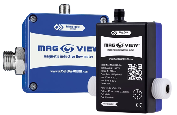 Magnetic flow meter Magnetic flow meter | 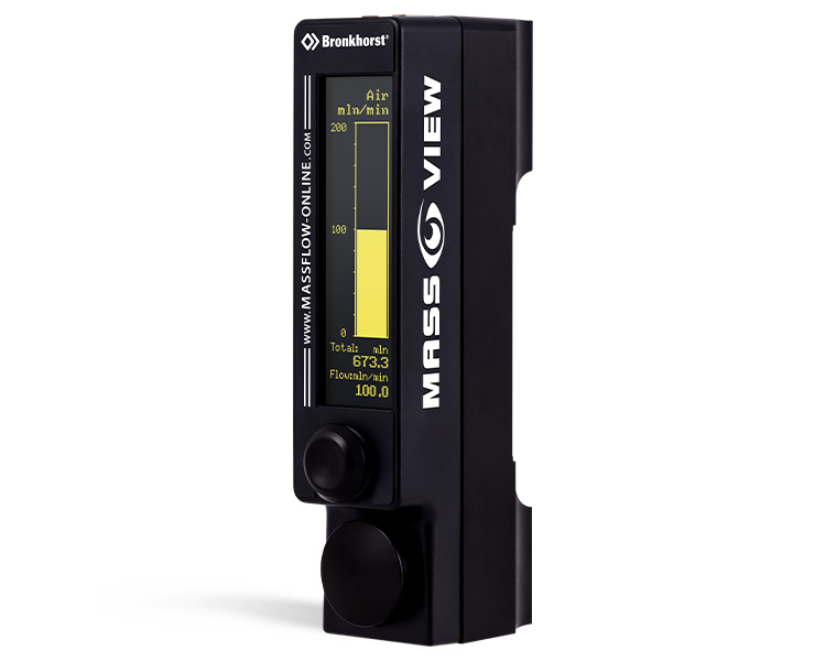 Variable area flow meter Variable area flow meter | 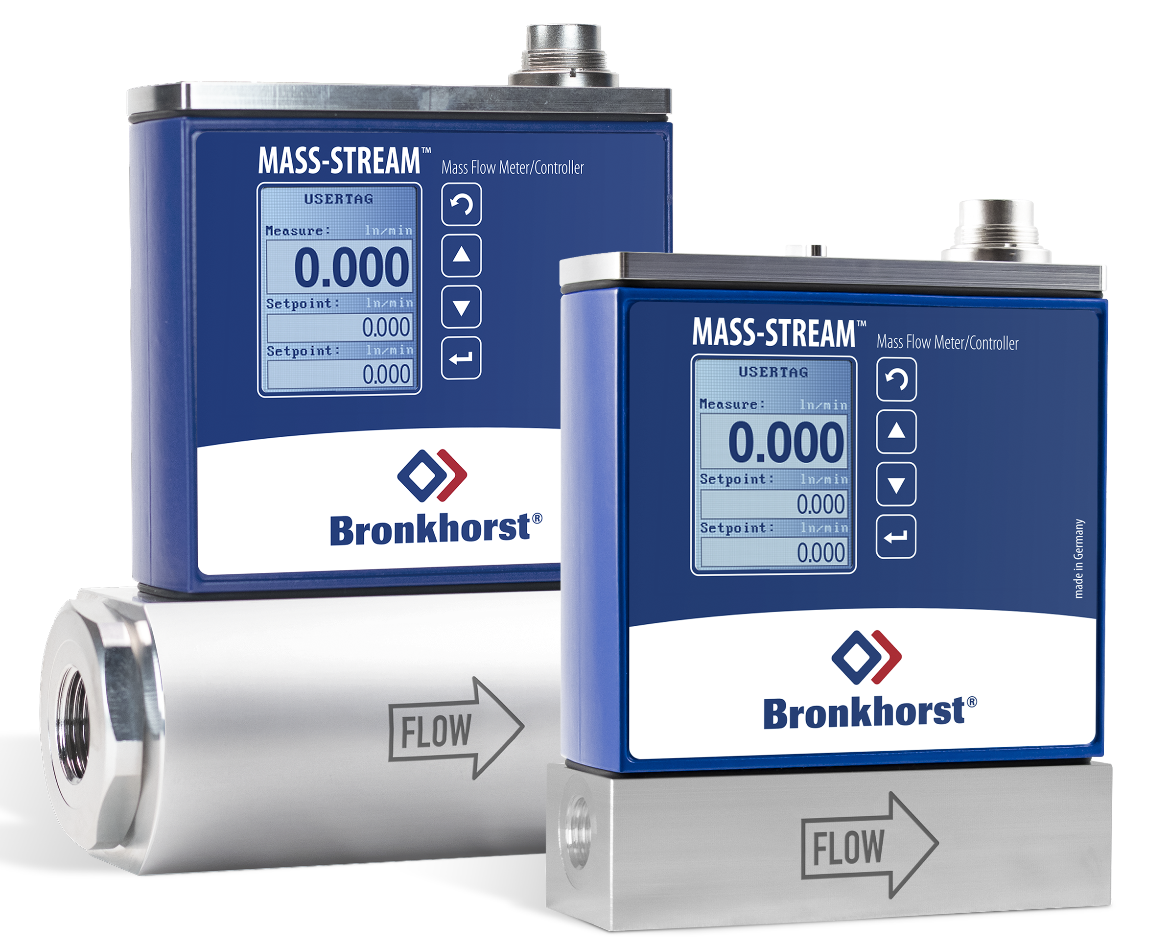 Thermal mass flow meter Thermal mass flow meter | 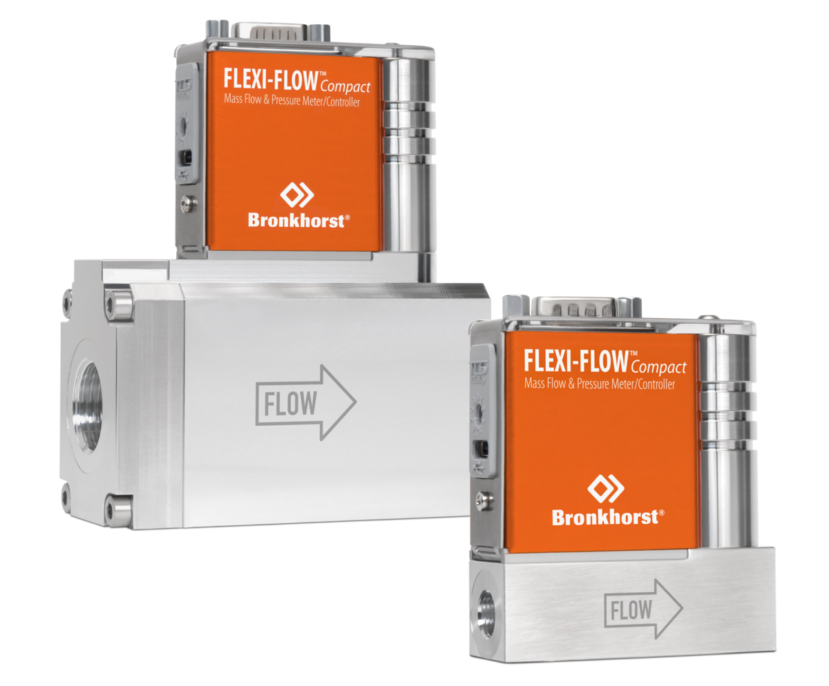 Smart thermal flow meter Smart thermal flow meter | |||
|---|---|---|---|---|---|---|
| Media | ||||||
 | Gases (Air, Ar, CO2, He, H2,N2, etc.) | ❌ | ❌ | ✅ | ✅ | ✅ |
 | Water-based conductive media (>20μs/cm) | ✅ | ✅ | ❌ | ❌ | ❌ |
| Deionized water / non-conductive media | ❌ | ✅ | ❌ | ❌ | ❌ |
| Specifications | ||||||
 | Output | Analog/Frequency | Analog/Frequency | RS-232/MODBUS/ 0-5Vdc | RS-232/4-20mA | Modbus-RTU / FLOW-BUS Bluetooth |
 | Accuracy | ± 1.5% | ± 1-2% | ± 2% | ± 1.5% | ± ~1% |
 | Medium temperature | -20…90 °C | -10…140 °C | 0…50 °C | 0…50 °C | 0…50 °C |
 | Display | ❌ | ❌ | ✅ | ✅ | ❌ |
 | Max pressure | 10 bar / 16 bar(g) | 12 bar(g) | 10 bar(g) | 10 bar(g) | 16 bar(g) |
 | Price | starting with € 550,- | starting with € 195,- | starting with € 799,- | starting with € 1.330,- | starting with € 1.250,- |
| Product page | View MAG-VIEW | View LIQUI-VIEW | View MASS-VIEW | View MASS-STREAM | View FLEXI-FLOW | |
Not sure which type fits your application? Get free advice from our specialists →
How to choose the right flow meter type
Magnetic inductive
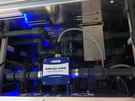 Magnetic flow sensors convert the velocity of a flowing fluid, water for example, into a measurable electrical signal that is proportional to the flow rate.
Usually magnetic flow meters have no moving parts or internal flow path obstructions, so they are easy to maintain.
Magnetic flow meters are typically specified to be the same size as the upstream and downstream piping; there is virtually no pressure loss through the flow meter, which can be very advantageous for some flow streams, like thicker slurries.
In our shop we have a few models (MVM-005-QA / MVM-001-Px / MVM-002-Px / MVM-030-Px) that have a narrowing slid in the piping to increase the flow velocity, this way we improved the accuracy of the meter.
Faraday's Law of Electromagnetic Induction
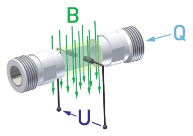 Fluid passes through the magnetic flow meter in a straight line through the piping of the sensor.
The cylindrical piping also allows a constant and directional magnetic field to be established across the diameter of the flow path.
The magic that creates the flow signal is based in the magnet!
The magnetic flow meter is surrounded by an iron-core, permanent magnet that establishes a magnetic field with lines of magnetic flux which pass vertically through the entire cross-section of the pipe and the flowing fluid.
The flowing fluid passes through these lines of magnetic flux at a 90-degree angle, perpendicular to the lines of magnetic flux.
In 1831, Michael Faraday observed that a voltage is induced across any conductor as it moves at right angles through a magnetic field, and that the voltage is proportional to the velocity of that conductor. This is called Faraday's Law of Electromagnetic Induction.
Vortex
Smart and lightweight vortex meter for water-like liquids
The LIQUI-VIEW Base series operates on the vortex principle.
The obstruction (bluff body) placed in the flow of the liquid sheds vortices downstream at a frequency proportional to the velocity of the liquid.
A piezoelectric sensor detects the vortices and creates electrical pulses which are proportional to the liquid flow rate.
LIQUI-VIEW Base provides the output either with frequency or analog output (4-20 mA).
The latter version can additionally be equipped with a bright, wide-angle, easy-to-read display for local readout purposes.
As the working principle of the instrument allows it to be mounted in any position, the structural design of the display makes it possible to rotate it through 180 degrees.
Thermal
How does a thermal mass flow sensor for gases work?
A thermal mass flow sensor measures the mass flow of a gas by using heat. A small heater warms the flowing gas, while a temperature sensor measures the heat carried away by the gas.
The higher the gas flow, the more heat is carried away. The sensor compensates for this by supplying more energy to maintain a constant temperature difference (ΔT).
The amount of energy required is directly related to the gas mass flow rate.
Constant Temperature Anemometry (CTA)
Many inline thermal mass flow meters (MASS-VIEW and MASS-STREAM) use Constant Temperature Anemometry (CTA), also known as the direct through-flow principle.
Unlike bypass-based flow meters, the gas flows directly over the sensor without being diverted through a bypass.
The sensor typically consists of two probes:
- A heater that adds heat to the gas
- A temperature sensor that measures the resulting temperature
The electronics continuously maintain a constant temperature difference between the two probes. As the gas flow increases, more heat is carried away and more power is needed to maintain this temperature difference.
In this way, the power required by the heater provides a direct indication of the gas mass flow rate.
MEMS-based thermal mass flow measurement
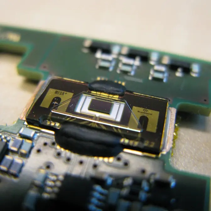 The FLEXI-FLOW uses a compact MEMS-based thermal sensor to measure the mass flow of gases directly in the flow channel.
The sensor uses tiny heating elements and temperature sensors to detect how much heat is carried away by the flowing gas. Higher gas flow means more heat is transferred, allowing the sensor to accurately determine the mass flow rate.
MEMS technology makes this measurement principle highly compact while also enabling the FLEXI-FLOW to measure mass flow, temperature and pressure in a single device.